简体中文
简体中文 English

Products
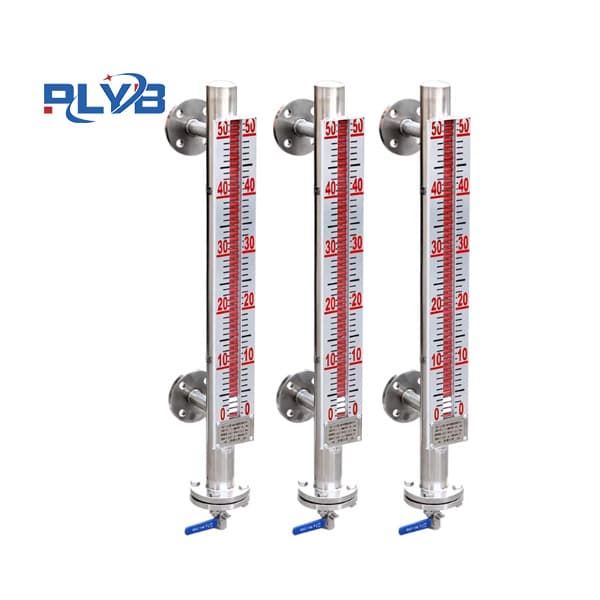
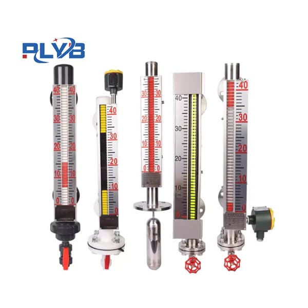
Side-mounted magnetic float level gauge
- Product Description
-
UHZ-62C series side-mounted magnetic float level gauge
1. Functions and Scope of Application
The UHZ-62C series side-mounted magnetic float level gauge is also known as the side-mounted column flipping level gauge (hereinafter referred to as the level gauge). Used for liquid level detection of liquid media in various pressurized (or open) liquid storage equipment (towers, cylinders, tanks, spherical containers, and boilers) in industrial processes. It can display the operating status and level heights of various liquids in place. Equipped with a level transmitter, it can transmit the liquid level position signal over a long distance. Automatic control and measurement of liquid level are achieved through certain electrical devices.
The level gauge is a reliable and safe detection instrument. Due to the magnetic coupling isolation and sealed structure, It is especially suitable for detecting flammable, explosive, and corrosive toxic liquid levels. This makes the liquid level detection method in originally complex environments simpler, more reliable, and safer.
The level gauge features a direct-reading feature for local display. No need to combine multiple level gauges. It has a single unit for full-scale measurement. The device has advantages such as fewer drill holes, clear display, prominent markings, and intuitive readings. When the level gauge is directly equipped with a display instrument, the intermediate signal transmission required for signal detection in the system can be eliminated, thereby improving transmission accuracy.2. Working principle of the UHZ-62C series side-mounted magnetic float level gauge
The level gauge uses the principle of a communicator. The liquid inside the container is introduced at an equal level into the main tube of the level gauge. The floating ball assembly inside the main tube is based on the principles of buoyancy and magnetic coupling. A flipping column that reflects magnetic phenomena is attached to the outside of the main tube to display the liquid level position. As the liquid level inside the literary tube changes, the height of the float assembly also changes accordingly. This causes the flap column outside the main pipe to flip 180 degrees. When the liquid level rises, the column changes from white to red; when the liquid level drops, the column changes from red to white. The red and white boundary positions on the display represent the actual height of the medium liquid level inside the container.
3. UHZ-62C Series Side-Mounted Magnetic Float Level Meter Features
1. Suitable for liquid level measurement of liquid media inside containers. In addition to on-site display, it can also be equipped with remote transmission transmitters, level controllers, and other functions.
2. The display is intuitive and eye-catching, with the display direction adjustable according to user requirements.
3. Large measurement range, not limited by container height.
4. The display component is completely isolated from the measured medium, ensuring good sealing, reliability, and safety.
5. Simple structure, easy installation, and easy maintenance.
6. Corrosion-resistant and explosion-proof.4. UHZ-62C Series Side-Mounted Magnetic Float Level Meter Technical Parameters
1. Measurement range: 0-300mm, 0-6000mm
2. Measurement accuracy: ±10mm
3. Medium density: ≥0.5g/cm3
4. Working pressure: 1.0, 1.6, 2.5, 4.0MPa
5. Operating temperature: A=80°C, B=120°C, C=300°C
6. Medium viscosity: ≤0.4 Pa·S (under medium conditions, L-pair medium with high viscosity or tends to crystallize at low temperatures should use a heating jacket)
7. Measurement boundary specific gravity difference: ≥0.15g/cm3
8. Factory connection flange dimensions: DN20 PN2.5 (metric pipe).
9. The connection flange follows the flange standard HG20592-20635-97 issued by the Ministry of Chemical Industry in 1998. If using other flange standards, please specify this when ordering. Flange connection hole layout shape: square.5. Selection of relevant parameters for the UHZ-62C series side-mounted magnetic float level gauge
Anti-corrosion materials (Table 1)
Codename
Name
Scope of application
PVC
Polyvinyl chloride
Water, sewage, and slightly corrosive liquids
PP
Polypropylene
Resistant to acids, alkalis, greases, oils, and oils
PE
Polyethylene
Resistant to enenoic acid, alkali, alcohol, and gasoline solvents
PTEE
Polytetrafluoroethylene
Resistant to all chemicals
PVDF
Polyvinylidene fluoride
Resistant to oils, greases, and acidic and alkaline solvents
Comparison Table of Common Domestic and International Stainless Steel Materials (Table 2)
China
United States
Germany
Japan
1Cr18Ni9Ti
321
1.4783
SUS32
0Cr18Ni2Mo2Ti
316
1.4571
0Cr17Ni12Mo2
316
1.4401
SUS316L
0Cr17Ni14Mo2
316L
1.4435
SUS316
0Cr18Ni9
304
1.4301
SUS304
Comparison Table of Liquid Media Density and Sinker Distance (Table 3)
Liquid medium density
sinking the tube spur
Commonly used liquid media
0.45~0.60
450~600
Liquefied petroleum gas and liquid ammonia
0.61~0.74
300~500
Gasoline, butadiene
0.75~0.85
250~300
Methanol, light oil, xylene
0.86~0.99
220~250
Propanol, beer
1.00~1.10
200~220
Water, acetic acid
1.11~1.25
170~200
Hydrochloric acid, tar
1.26~1.39
160~170
Liquid alkali, 20% dilute sulfuric acid
1.40~1.59
150~160
Liquid chlorine, chloroform, concentrated sulfuric acid
1.60~2.00
120~150
Fluorine oil, 98% sulfuric acid

6. Application Instructions for the UHZ-62C Series Side-Mounted Magnetic Float Level Gauge
1. Install a shut-off valve between the side-mounted liquid level and the upper and lower separator pipes of the tested container to open or fully install the level gauge, which also facilitates level maintenance. When the upper and lower shut-off valves are closed, you can open the drain flange at the bottom of the level gauge or remove the drain screw and fill in clean water to clean the main body of the level gauge.
2. Install the level gauge. The flange centerline is perpendicular to ∠4‰. When the measuring range exceeds 3 meters, consider adding a central reinforcement flange (or ear climber) for fixed support to increase strength.
3. The cross-sectional area of the core wire connecting the remote level meter transmitter and secondary instruments should be greater than 0.8mm². When laid parallel to the AC power supply, at least 20 cm should be maintained. It is best to lay the shield through iron pipes alone or use shielded two-core cables, with only one end of the shielding grounded.
4. select a level controller, with contact capacities designed for resistive loads. If using non-resistive or high-power loads, intermediate relays must be used for switching.
5. When the liquid medium contains suspended impurities and magnetophilic substances, this level gauge is not suitable (as these impurities may cause jamming in the float assembly).
6. In the external structure diagram, "L1" represents the "sinker distance" of side-mounted level gauges. Users must understand this parameter is related to medium density. According to the principle of buoyancy, the length of the float assembly is related to medium density. Therefore, when selecting and designing, different media have different L1 parameters. See Table 3 (for reference only).
7. UHZ-62C Series Side-Mounted Magnetic Float Level Gauge Installation, Use, and Maintenance
1. The level gauge must be installed vertically to ensure the float ball assembly can move freely up and down inside the main pipe (see Figure 3).
2. It is best to install a shut-off valve between the container and the level gauge to facilitate cleaning and maintenance when cutting off materials.
3. No magnetic conductors are allowed near the main tube of the level gauge, otherwise it will directly affect the normal operation of the level gauge.
4. After installing the level gauge, it needs to be calibrated with a magnet. Guide the flipping column once so that below zero it shows red and above zero shows white.
5. When putting the liquid level gauge into operation, first open the lower liquid drain pipe valve to allow the liquid medium to smoothly enter the main pipe, preventing the liquid medium from rising rapidly with the float assembly, which could cause column tipping, black center failure, or random tipping (if this occurs, re-correct it with a magnet once the liquid level stabilizes during the rise and fall).
6. During transportation, to prevent damage to the float ball assembly, remove the float ball assembly from the main tube of the small liquid level gauge before leaving the factory. After the level gauge is installed, open the bottom drain flange, then reinstall the float ball assembly into the main pipe. Note that the heavier end of the float ball assembly faces upward and cannot be installed upside down.
7. Depending on the medium, the drainage flange can be regularly opened to clean sediment inside the main pipe.
Related Products
Product Inquiry
Please leave your information, and we will contact you as soon as possible after receiving it. Thank you for your support!